Design
The times when entire buildings were conceived in the mind of an experienced craftsman have thankfully passed. The ever growing needs of both the time of completion and the quality of a project, combined with modern architectural challenges that require more complex structures, have introduced in our field the use of computer equipment.


A series of specialised software for analysis and steel modelling is able to meet the everyday design challenges. Our company currently owns two licences of the most recognised and prevalent worldwide software system StruCad. By using this software, 3D modelling is accomplished with maximum accuracy and speed of any design, preparing also all supporting construction drawings for the project. This steel detailing includes:
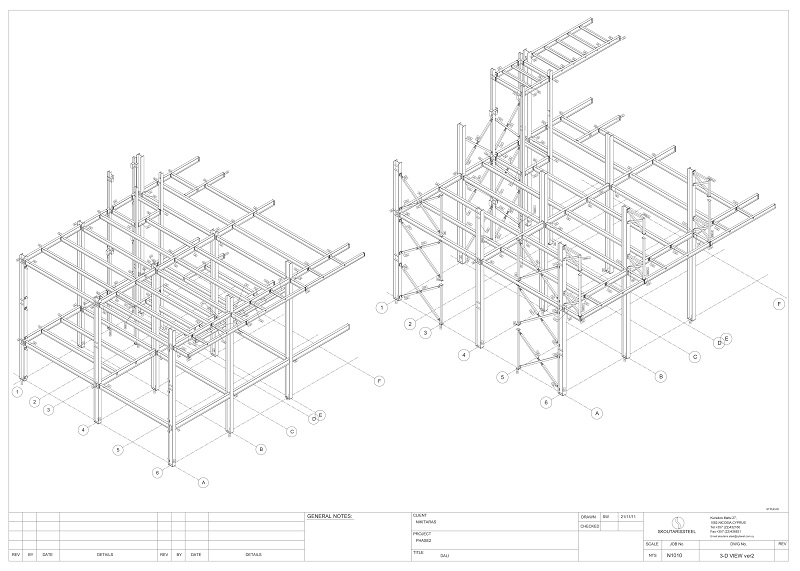
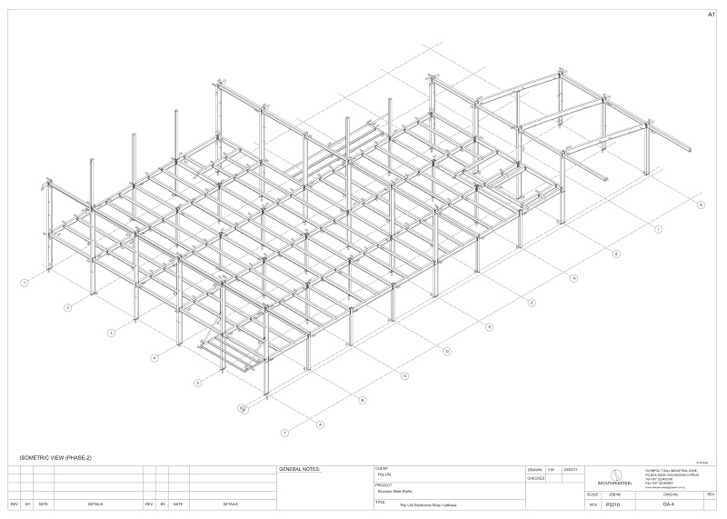
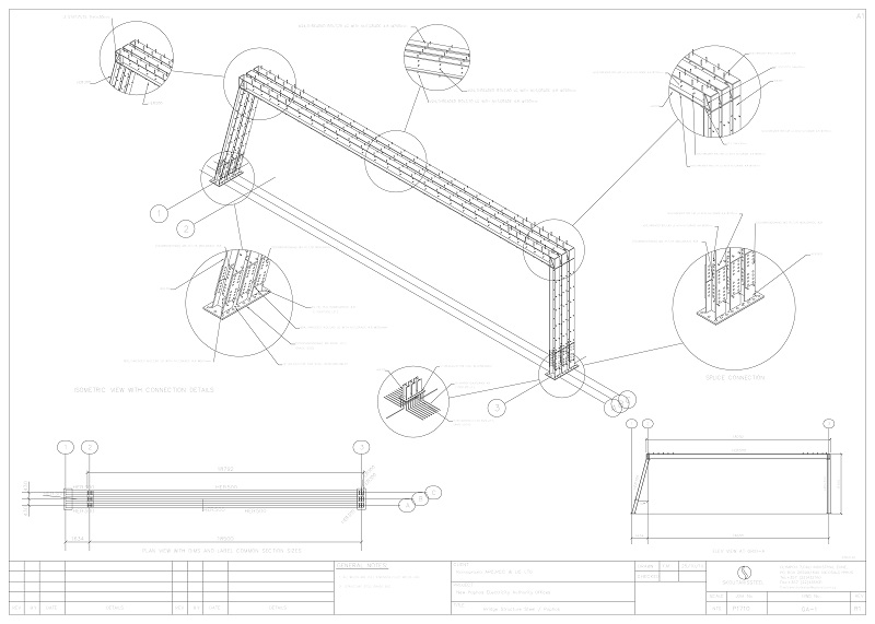
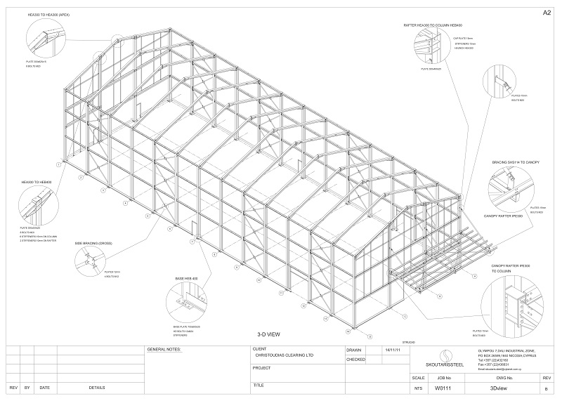
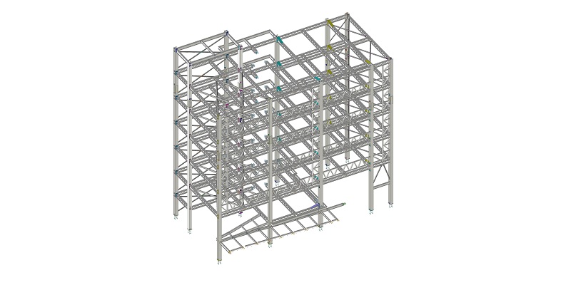
General arrangements
Illustrating the general form of the structure in isometric views, as well as dimensioned side views and plans. All necessary architectural information is also listed (dimensions, spans, elevations, etc). Furthermore, close views on connections are presented to allow checks on all connection details of the structure (welding lines, bolts, etc.). These plans may be submitted to architects and engineers for consideration in conventional formats (dxf, dwg, pdf).
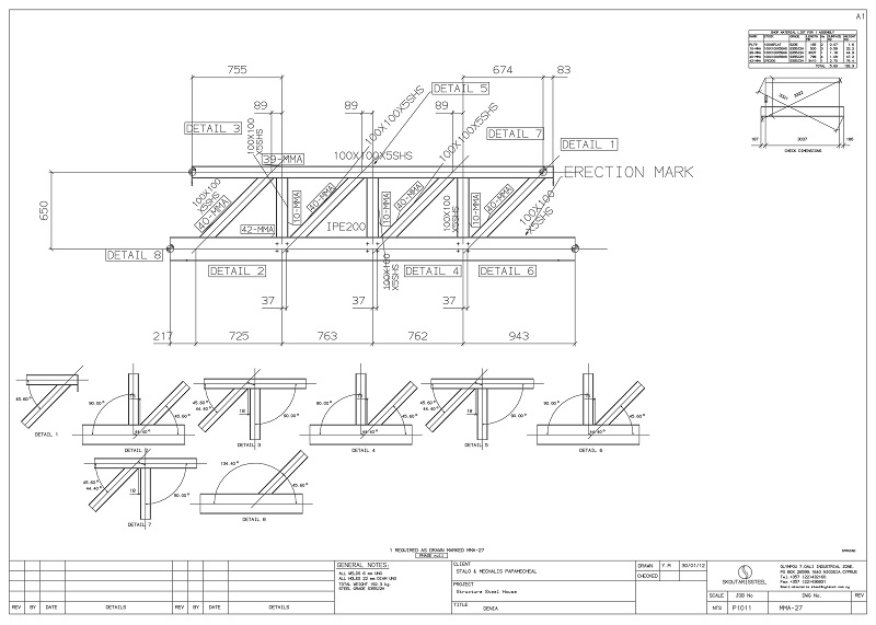
Shop drawings
The A to Z of the production process, since these drawings are generated separately for every member, presenting all necessary information for fabrication. The member shaft drawings and the fitting details provide every detail on the cutting (length, cutting angle) and puncture (hole diameter and positioning) of all members and connecting parts of the model. The members and fittings are welded together based on the fabrication drawings resulting precisely in ready for erection steel members correspondingly numbered. In cases where an assembly is required with two or more members, such as stairs, trusses etc, multi-member αssemblies are produced to give all the information regarding how they are connected.
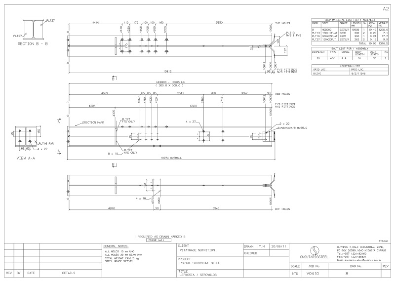
Material list
Useful lists of all the materials in need, from the structural steel members up to the bolts. A particularly helpful tool for the manufacturer for ordering the material as well as carrying a quantity analysis of the structure (number of members, total weight, cross sectional area, etc).
Exporting of DSTV files
A valuable aspect of the detailed design is the production of DSTV files. It is basically a digitalisation of shop drawings in order to be successfully integrated with CNC machinery. In this way, the design process contributes decisively to the further automation of production.
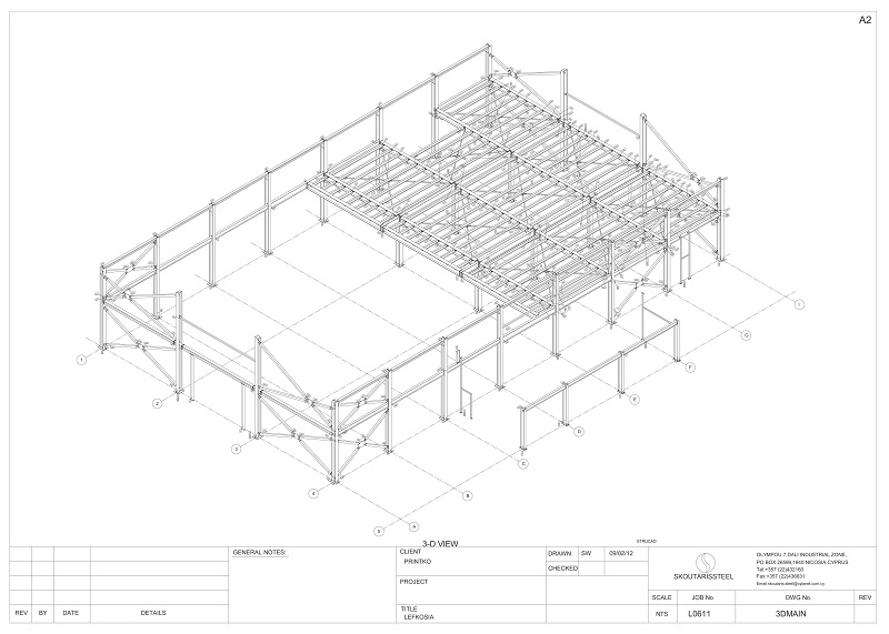
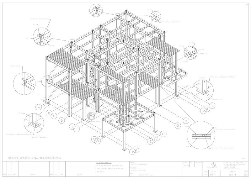
Erection Drawings
A range of perspective views presents the model with each member distinctively marked. Each component of the structure is identified and the sequence of erection is then specified, resulting in a simplified and definitely safer construction process.